Description
Simplest and Easily Operated
Smooth Testing Experience
The lift-up angle of the hammer after impact is automatically measured, and the impact energy is calculated. Operation methods can be selected from touchscreen control (Model No.258-D) or PC control (Model No.258-PC).
The No.258-D model was updated with new software in 2024, significantly improving operability and user experience.
Safety Cover Specifications
Full-Cover Specification
The testing area can be completely enclosed with a safety cover, ensuring both the hammer does not come into contact with the operator and preventing test sample scatter. Hammer release and other operations can be performed via the touchscreen.
| Standards |
JIS/ISO |
ASTM |
| Reference Standards |
JIS K 7111-1,ISO 179-1 |
JIS K 7110,ISO 180 |
ASTM D6110-10 |
ASTM D256-10 |
| Testing Methods |
Charpy Impact Test |
Izod Impact Test |
Charpy Impact Test |
Izod Impact Test |
| Hammer Energy(J)*1 |
0.5, 1, 2, 4, 5 |
7.5, 15, 25*2 |
1, 2.75, 5.5, 11, 22 |
2.7-21.7 |
| Anvil Spacer |
Required |
– |
– |
– |
– |
| Impact Velocity |
2.9m/s(±10%) |
3.8m/s(±10%) |
3.5m/s(±10%) |
3.46m/s |
3.46m/s(3.5m/s) |
| Hammer Lift Angle |
150° |
| Hammer |
Refer to the respective sections below for details. |
| Anvil |
Refer to the respective sections below for details. |
*1 Hammer capacities other than the standard options can also be manufactured. Please inquire if hammers in kgf·cm units are required.*2 Hammers with a capacity of 50 J are not available.
Hammer
Charpy Hammers
| Standard |
Potential Energy |
Impact Velocity |
Angle of Striking Edge |
Radius of Striking Edge |
ISO/
JIS |
0.5J |
2.9m/s(±10%) |
30±1° |
2.0±0.5mm |
| 1J |
| 2J |
| 4J |
| 5J |
| 7.5J |
3.8m/s(±10%) |
| 15J |
| 25J |
| ASTM |
2.7-21.7J |
3.46m/s |
45±2° |
3.17±0.12mm |
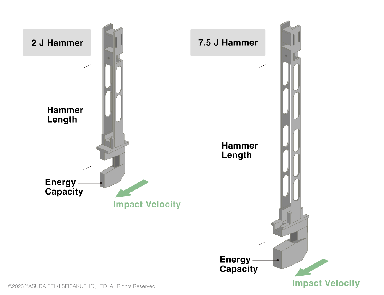
The characteristics of the Charpy hammers differ between the test standards as shown in the table above. In ISO and JIS standards, the hammer length changes according to the impact velocity. Therefore, the same hammer cannot be used to create, for example, a 4 J impact and 7.5 J impact. Two different hammers must be prepared.
Izod Hammers
| Standard |
Potential Energy |
Impact Velocity |
Radius of Striking Edge |
ISO/
JIS |
1J |
3.5m/s(±10%) |
0.8±0.2mm |
| 2.75J |
| 5.5J |
| 11J |
| 22J |
| ASTM |
2.7-21.7J |
3.46m/s(3.5m/s) |
0.8±0.2mm |
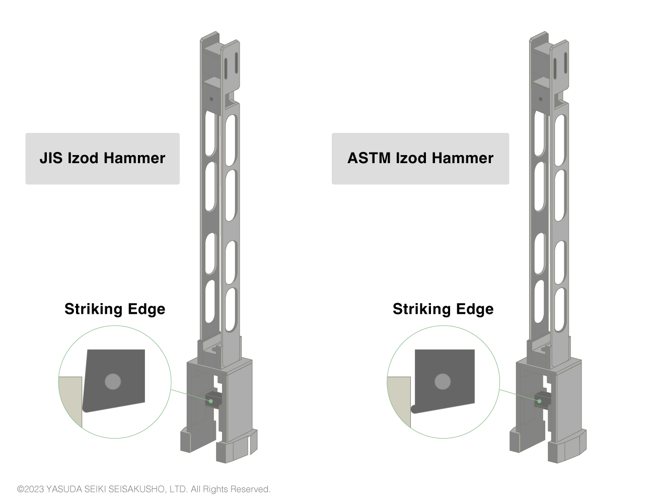
The same hammer is sometimes used between ISO (or JIS) and ASTM impact tests as the details of the hammers specified in the two standards are similar. However, to be precise, the shape of the striking edge differs between the standards as shown in the above image. Therefore, to conform to the test standards, hammers that match the test standard shall be used.
Anvil
Charpy Anvil
| Symbol |
Parameter |
ISO/JIS |
ASTM |
| ー |
Parallelism between long axis of test sample and reference plane |
±4/1000 |
ー |
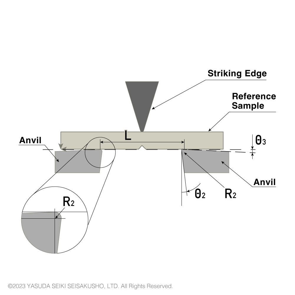
| R2 |
Radius of curvature of anvils |
1±0.1 mm |
3.17±0.12 mm |
| θ2 |
Angle of taper of anvils |
10±1 ° |
0 |
| θ3 |
Angle of slope of anvils |
5±1 ° |
0 |
| ー |
Angle of supports and anvils |
90±0.1 ° |
90° |
| L |
Span between sample supports |
62±(0.5/0) mm |
101.6±0.5 mm |
The shape of the anvil differs between ISO (or JIS) and ASTM standards. Therefore, to perform both ISO and ASTM standardized tests, two different anvils shall be prepared.
Izod Anvil
| Symbol |
Parameter |
ISO/JIS |
ASTM |
| ー |
Sample angle |
90±2 ° |
ー |
| ー |
Parallelism with face of reference sample |
±0.025 mm |
ー |
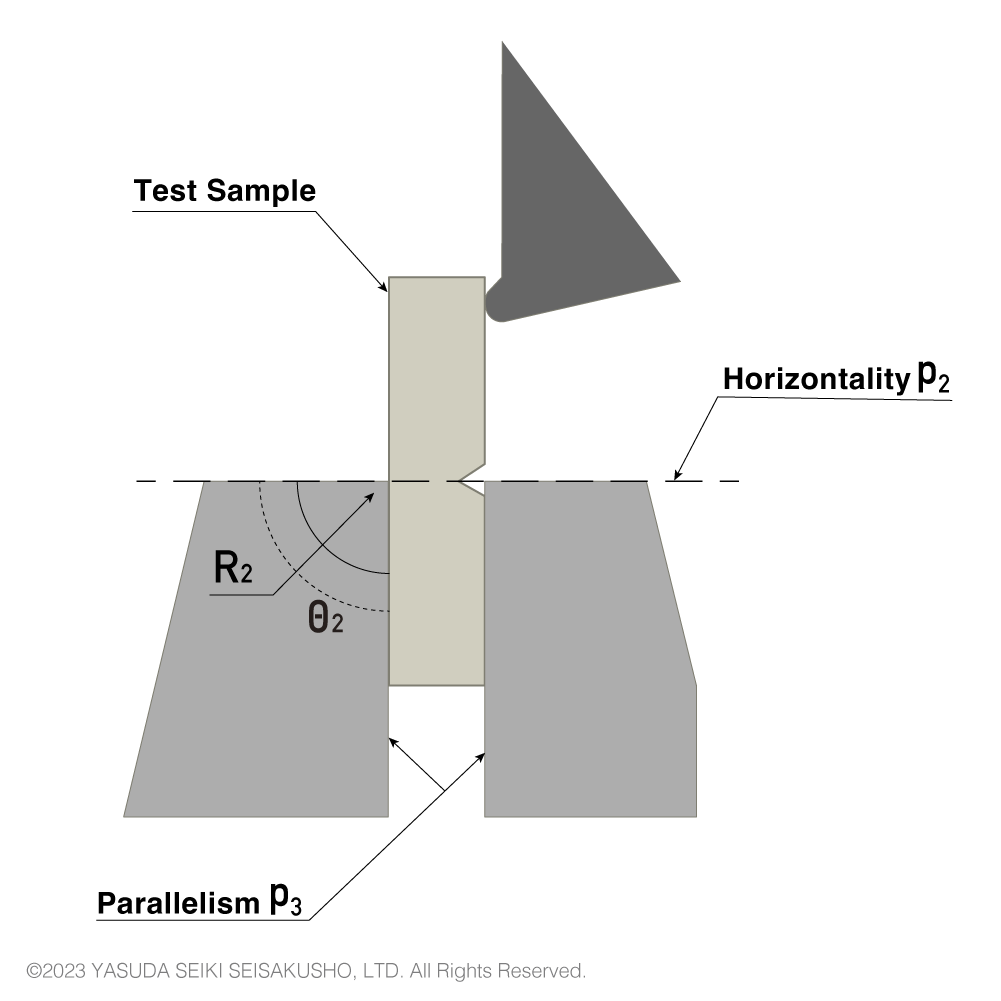
| P2 |
Horizontality of top surface of vise |
±3/1000 |
ー |
| θ2 |
Angle between support block and top surface of vise |
90±0.5 ° |
ー |
| P3 |
Parallelism in horizontal and vertical direction |
±0.05 mm |
ー |
| R2 |
Top edge radius of support |
0.2±0.1 mm |
0.25±0.12 mm |
In strict terms the anvil shapes differ between ISO (JIS) and ASTM standards, but are sometimes used mutually as the differences are minor.


Reviews
There are no reviews yet.